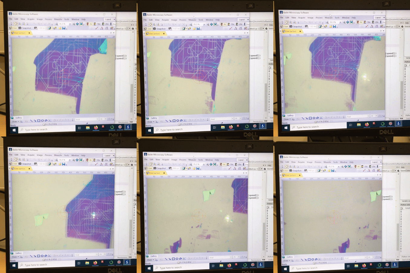
Before starting to stack your 2D materials you should think in what type of stack you want to do and what are the more appropriated methods to do so. Here are some examples:
Stacking to a fragile substrate (e.g., TEM grid): For this you migth want to use the membrane transfer. This one consist in exfoliating in a polymer and releasing this as a membrane to later deposit it the target substrate. You can find all the details in this article and its supplementary.
Stamping: This is the so called dry technique and consists in using a 2D material to pick up sucesive 2D materials. One of the first publications to explain the technique is here. The animation below is very self-explanatory of the process.
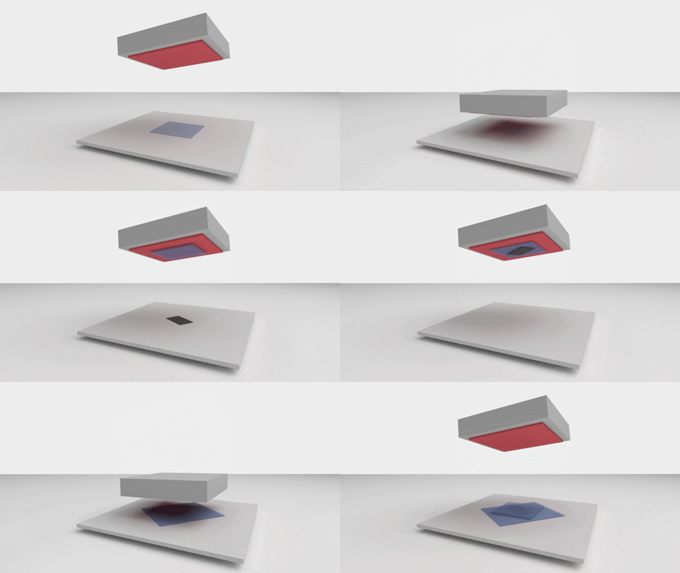
The process consist in picking up the different 2D materials one at the time using a combination of polymers (e.g., PPC or PC on top of PDMS) or a SiN membrane (see here). After picking up all the different 2D materials the polymer is melted on top and the stack deposited on the substrate of your preference.
The hot pick up technique (under construction):
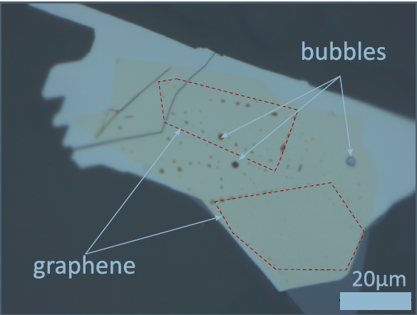
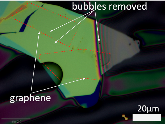
Bubble squeezing: After picking up all the layers you might realize that some bubbles are formed in your stack. This are formed of tape residues, water and/or air. To clean up your stack you can squeeze the bubbles mechanically at higher temperatures. The techniques to do this (either with PC or PPC) are described in the following article. As you can see in the pictures bellow the technique is very effective to get ride of bubbles
PDMS stamping: As you could see all along this post we have mentioned two main polymers PC and PPC that are deposited on top of PDMS, these are the most used ones in for the stacking. However, there are other polymers also used for this, in the following table we summarize them and give you their main use and temeprature range to be used.
| Polymer | Temperature pick-up | Temperature release | Cleaning |
| PPC Ploy(propylene carbonate) | 40 oC | 80 oC – 120 oC | Annealing in vacuum at 360 oC |
| PC Polycarbonate | 90 oC | 185 oC | Chloroform |
| PET Poly(ethylene terephthalate) | 60 oC | 130 oC | |
| PVC Poly(vinyl choride) | 70 oC | 130 oC | |
| PCL Poly(caproalactone) | 30 oC | 60 oC |
Cutting 2D materials
Now that you have the basic notions of stacking you can start preparing twisting heterostructures. For twisted graphene structures the most widely used technique is the tear and stack technique detailed here. However, the tear part of this technique has been proven to give many problems of breaking the layers. A clear improvement in reproducibility has come with the implementation of different techniques to cut graphene before starting the stacking. Here we list few of them:
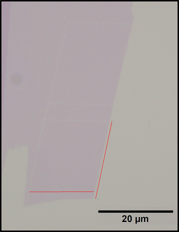
- AFM cutting: the anodic oxidation nanolithography consist in applying a high frequency (>10 kHz) AC voltage to a Pt/Ir coated AFM tip (e.g., Arrow-NCPt-50, available here), to design on it a desired pattern, the resolution of the cut can go down to 10 nm, which makes it particularly interesting for polymer-free lithography of graphene. The full explaination can be found in this research article. An example of what can be done in graphene:
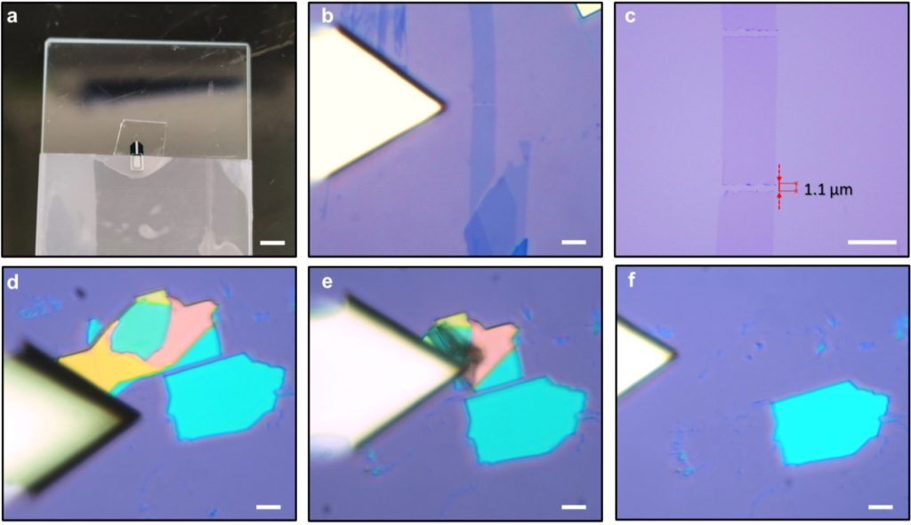
- AFM tip on PDMS cutting: A cheaper version of this technique can be achieved by sticking an AFM tip to a PDMS stamp. The PDMS stamp is placed in a transfer station, the optical microscope of this allows you to see when the tip enters in contact by a change in its reflectance. Once in contact the stage is moved to cut the graphene or move pieces of 2D materials that you don’t want in the way, as depicted in the picture below.
- Laser cutting: by using a laser (filters between 500 nm and 600 nm) we can perform cuts in graphene and graphite layers in a fast and easy way. This technique was developed by Lutz Waldecker at RWTH and we added a joystick to to make it easier to use: